

 Cable Automotive / Marine
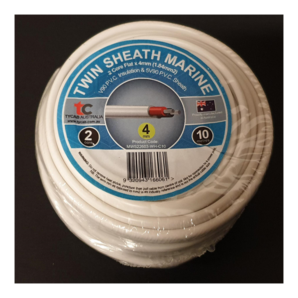
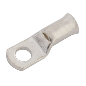 Cable Lugs
 Cable Lug Assortment Kits
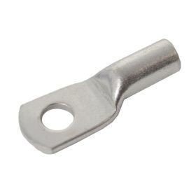 Cable Lugs Straight Wall Closed
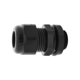 Cable Glands
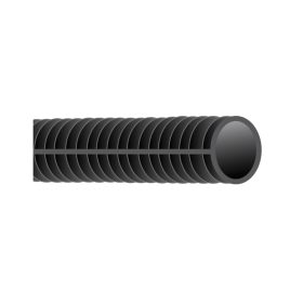 Convoluted Split Tubing
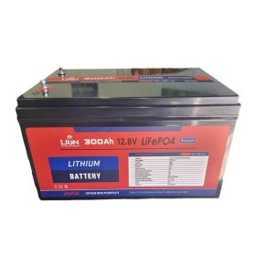 12/24v Products & Access

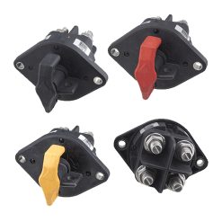
 Electrical Connectors
 Solar Powered Products
 LED Lights

 Tools
 Auto Parts & Categories
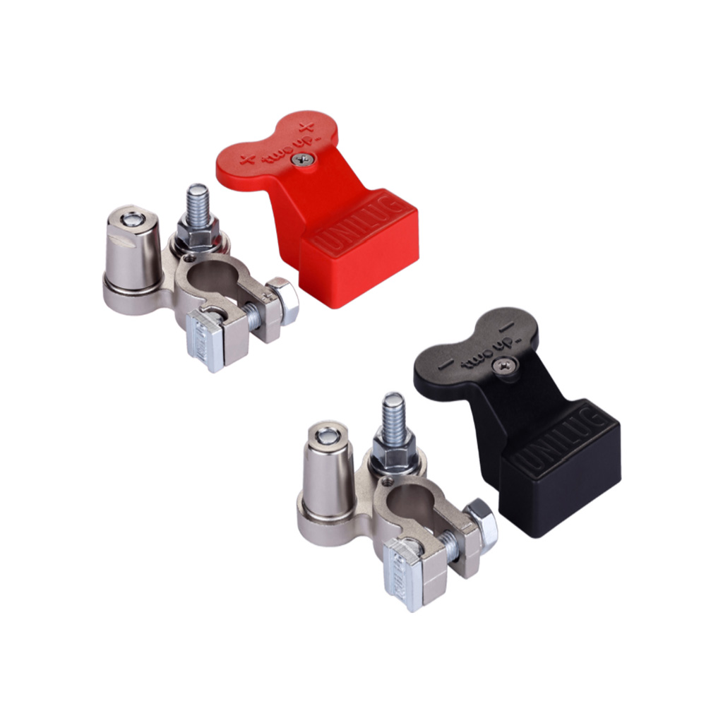

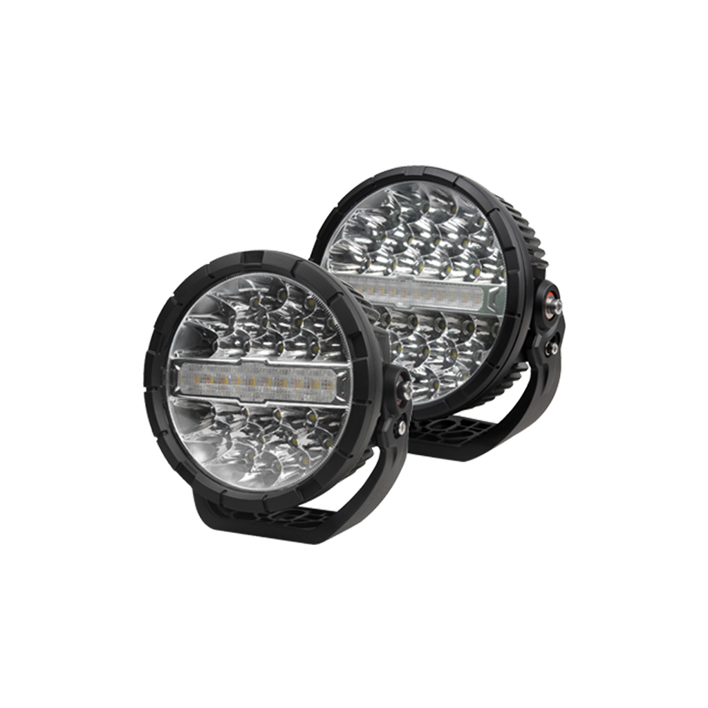
 Fittings
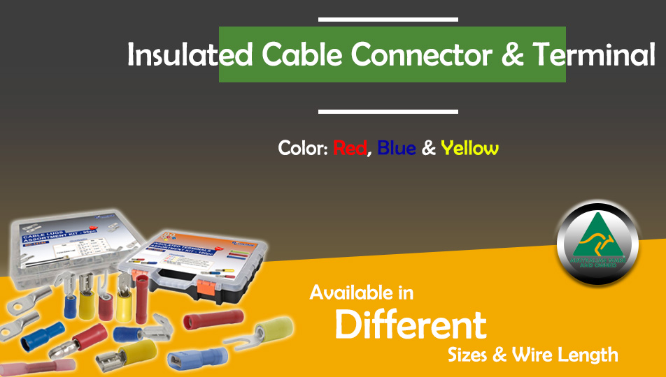
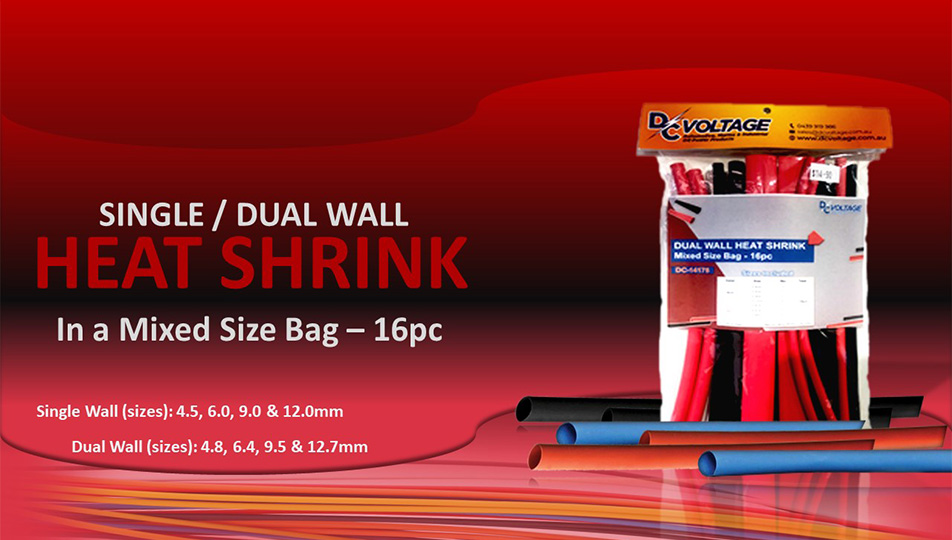
 Cleaning & Misc
 Clearance & Promotion
Latest News
How to Test Trailer Wiring Before You Tow
Jul
A trailer can look ready to tow while one failed earth, corroded pin or broken cable leaves you without brake lights on the road. Knowing how to test trailer wiring lets you isolate the fault before a trip, whether you are towing a box trailer, camper, caravan, boat trailer or work trailer.
The quickest approach is to test the tow vehicle and trailer as separate systems first. That prevents guesswork. If the vehicle socket is supplying the right power, the fault is on the trailer. If it is not, start at the vehicle wiring, fuse, relay or trailer control module.
What you need to test trailer wiring
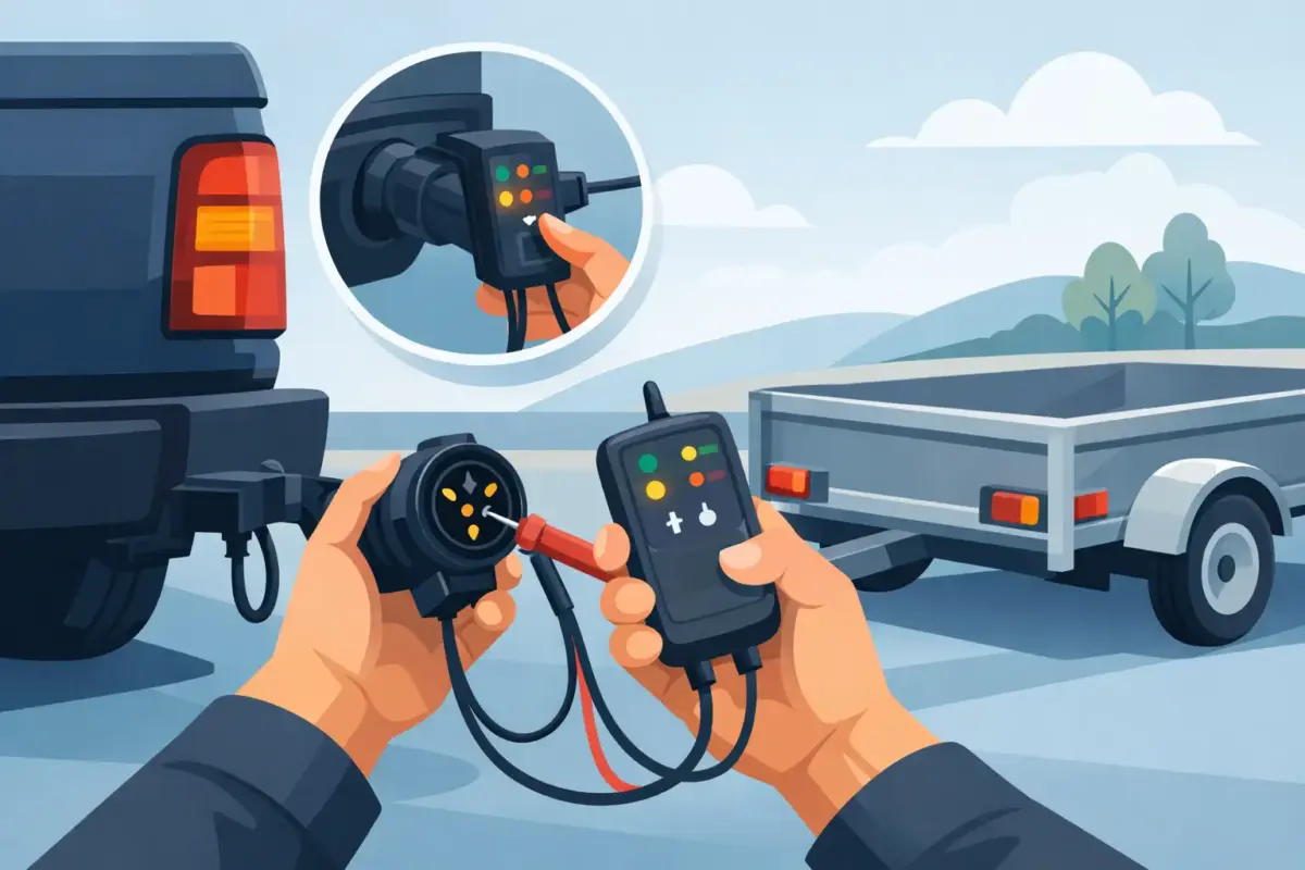
A digital multimeter is the most useful tool because it can check voltage, continuity and resistance. A 12V test light is also handy for a quick voltage check, although it will not identify a high-resistance connection as clearly as a multimeter. Keep a wiring diagram for your plug type nearby, plus a short length of cable or a known-good trailer plug tester if you have one.
Before testing, inspect the obvious items. Check that the plug is fully seated, pins are clean and not pushed back, cable insulation has not been crushed around the drawbar, and lights have not filled with water. On trailers that work hard on corrugated roads, the cable entry to the plug, junction boxes and lamp housings are common failure points.
Australian trailers commonly use a flat 7-pin plug, small round 7-pin plug, large round plug or 12-pin plug. Pin positions and wire colours are not always consistent on older trailers or modified vehicles. Never rely on wire colour alone. Confirm each terminal against the relevant plug diagram before applying power or probing pins.
Test the tow vehicle socket first
Park on level ground, select park or neutral, apply the handbrake and have an assistant operate the lights where possible. Do not allow test probes to bridge two terminals in the socket. A short circuit can blow a fuse or damage a vehicle body-control circuit.
Set the multimeter to DC volts, using a 20V range or auto-ranging mode. Connect the black probe to the earth terminal in the trailer socket, then touch the red probe to the terminal being tested. With the relevant vehicle function switched on, you should normally see close to battery voltage. Around 12V with the engine off and roughly 13.5V to 14.5V while charging is typical, depending on the vehicle.
Test each required circuit one at a time: left indicator, right indicator, tail and clearance lamps, brake lamps, reverse lamps if fitted, and auxiliary power where applicable. Indicators will pulse, so the meter reading may rise and fall. A test light makes pulsing indicator circuits easier to see.
If no voltage is present at one terminal, check the vehicle’s trailer-wiring fuse, relay, wiring harness connection and any smart-module settings. Late-model utes and SUVs may detect trailer load electronically, and some circuits will not behave like older hard-wired systems. In that case, use the vehicle manufacturer’s testing procedure rather than adding a jumper wire or bypassing a module.
Check the vehicle earth under load
A socket can show voltage on a meter and still fail once the trailer lights draw current. To test the earth properly, connect a test light or a load tester between the vehicle’s power terminal and earth terminal. A dim light suggests resistance in the earth path, corrosion in the socket or a weak vehicle earth connection.
This matters particularly with LED-equipped trailers. LEDs draw very little current, so they may appear to work despite an earth that is poor enough to cause problems later. Traditional globes place more load on the circuit and can expose an earth fault quickly.
Test the trailer plug and wiring
Once the tow vehicle socket checks out, unplug the trailer and inspect its plug closely. Green deposits, blackened terminals, loose terminal screws and split cable glands are all signs that the plug needs attention. A plug that has been dragged through mud, salt water or red dust is worth replacing rather than repeatedly repairing.
To check continuity, disconnect the trailer from the vehicle and turn off any auxiliary battery supply that could feed the circuit. Set the multimeter to continuity or resistance. Place one probe on a plug terminal and the other at the matching light fitting, junction point or cable end. A tone or very low resistance generally confirms a continuous cable.
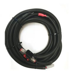
Move and flex the cable while watching the meter. If continuity cuts in and out, the conductor is often broken inside the insulation near the plug, drawbar clamp or a point where the loom has rubbed against steel. Replace the damaged section and protect the new run with suitable conduit, grommets and cable clamps. Twisting wires together and wrapping them in tape is not a durable trailer repair.
Check every circuit individually. If a circuit shows no continuity, work back from the lamp towards the plug until the break is found. If continuity is present between a power terminal and the trailer chassis when the circuit should be isolated, look for a pinched wire, water inside a lamp or damaged insulation causing a short.
Test the trailer earth properly
The earth is the first place to look when lights are dim, indicators flash with the brake lights, or several lamps stop working at once. Many trailers use the chassis as the return path, but painted, rusty or loose mounting points create resistance.
With the trailer connected, switch on the tail lights. Set the meter to DC volts and place the black probe on the vehicle battery negative terminal or a known-good vehicle earth. Touch the red probe to the trailer light housing earth point or the trailer chassis near the lamp. Ideally, the voltage drop should be very low. A reading approaching one volt or more under load points to an earth problem.
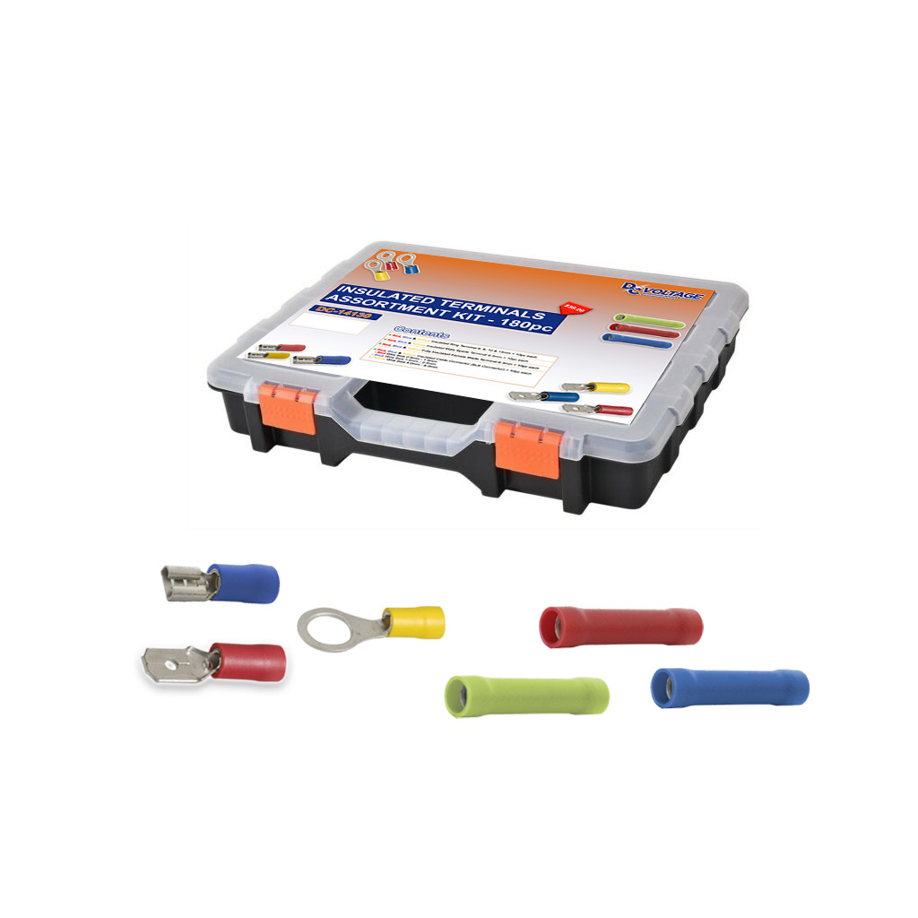
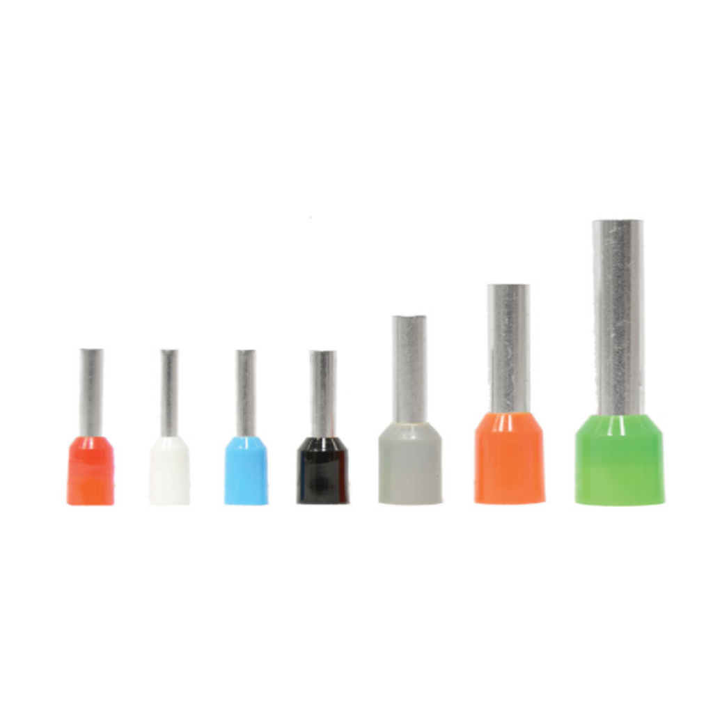
For a more reliable repair, run a dedicated earth conductor from the plug to a properly terminated earth junction, then branch it to each lamp rather than relying solely on the chassis. This is especially worthwhile for caravans, enclosed trailers and boat trailers exposed to moisture. Use correctly sized cable, crimp terminals suited to the conductor, and heat-shrink where weather protection is needed.
Check lights, connectors and lamp fittings
If power and earth are reaching the rear of the trailer but a lamp still does not work, the issue is usually inside the fitting. Remove the lens and look for a failed globe, loose LED connector, corroded contacts or water ingress. On combination lights, a faulty shared earth can make one function back-feed through another globe, producing strange results such as both indicators flashing together.
LED replacement lamps can create another variable. Some vehicle trailer modules monitor current draw and may report a failed globe or refuse to recognise a low-load LED circuit. A load resistor or compatible LED solution may be required, but fitting resistors creates heat and should be done correctly. Do not assume every LED issue is a wiring fault.
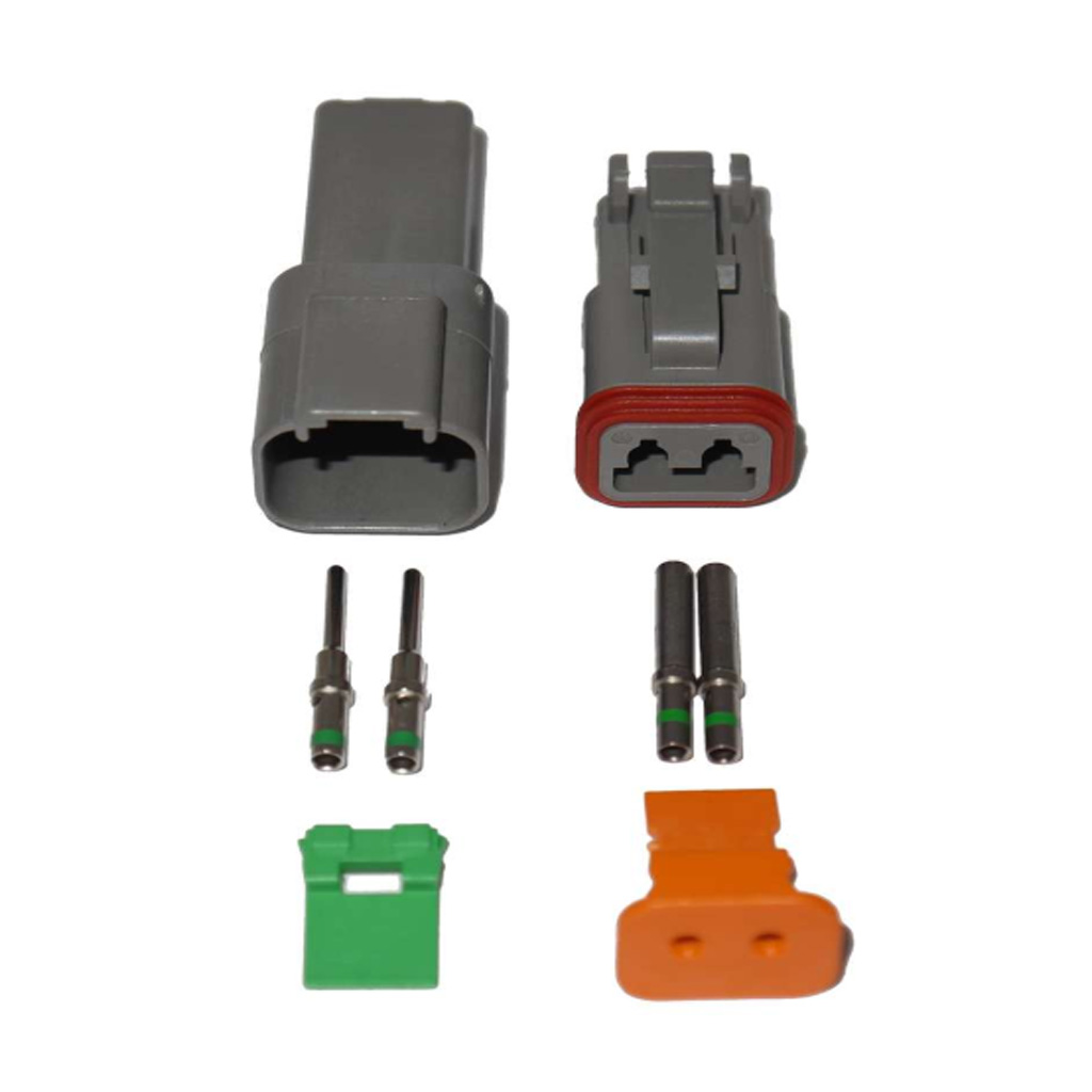
Also inspect any joiners beneath the trailer. Scotch-lock style taps and exposed screw connectors often become unreliable after water, vibration and dust. Sealed connectors, proper crimps and strain relief take longer to fit but save repeat repairs.
Testing electric brakes and auxiliary circuits
Electric trailer brakes need their own checks. With the trailer connected and safely chocked, activate the brake controller’s manual override. You may hear a faint hum from the brake magnets, but sound alone is not proof of correct operation. Check the brake circuit voltage at the trailer plug and at the brake wiring junction, then inspect each axle connection for damaged cable or loose terminals.
Brake controllers are proportional on many modern vehicles, so output voltage can vary with braking effort and controller settings. Follow the controller manufacturer’s setup process and carry out a low-speed brake test in a safe area. Never test brake wiring by connecting it directly to battery power unless the brake manufacturer specifically permits that procedure.
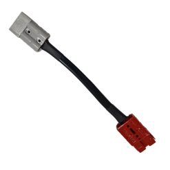
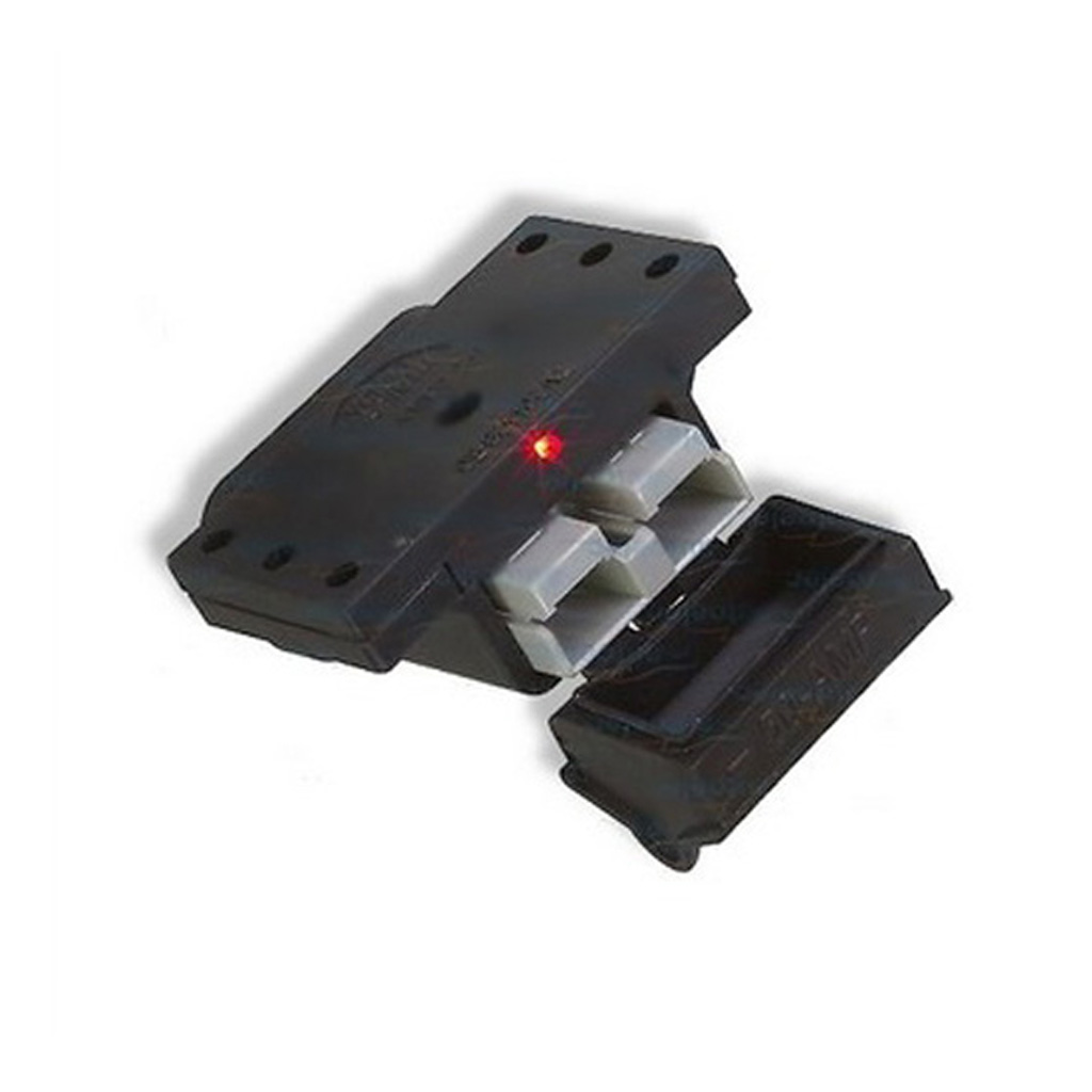
For auxiliary 12V feeds, check both voltage and cable size. A fridge feed, battery charging circuit or breakaway battery system can show voltage with no load but suffer a major drop once current is drawn. Long runs, undersized cable, poor Anderson-style connections and weak earths are usual causes. Test at the source and again at the appliance or battery input while it is operating.
Common trailer wiring faults and the practical fix
Most faults come down to a small group of issues: a corroded plug, failed chassis earth, broken drawbar cable, water-damaged lamp, incorrect plug termination or a blown vehicle fuse. Start with the simplest checks, but do not overlook cable condition just because a plug looks clean.
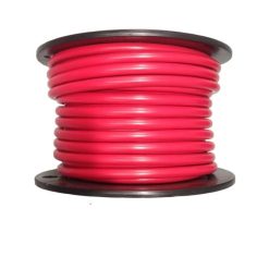
When replacing wiring, match cable size to the current draw and run length. Lighting circuits can use lighter cable than high-current auxiliary or charging circuits, while electric brakes require cable and protection sized for the number of magnets fitted. Route all cable away from sharp edges, moving suspension parts, exhaust heat and stone strike areas.
A clean test process is faster than swapping parts until something works. Check the vehicle socket, verify the trailer plug, prove the earth, then test each circuit under load. If you are rebuilding a loom or replacing tired connectors, Bluebar Industries stocks practical cable, plugs, connectors, protection and workshop tools suited to trailer and touring repairs. Finish with a full light check before every tow – it takes minutes and can prevent a roadside fault when the trailer is loaded and the trip is already underway.