

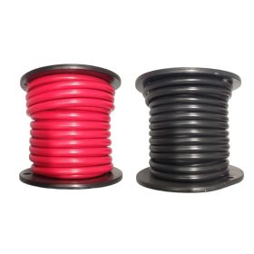
 Cable Automotive / Marine
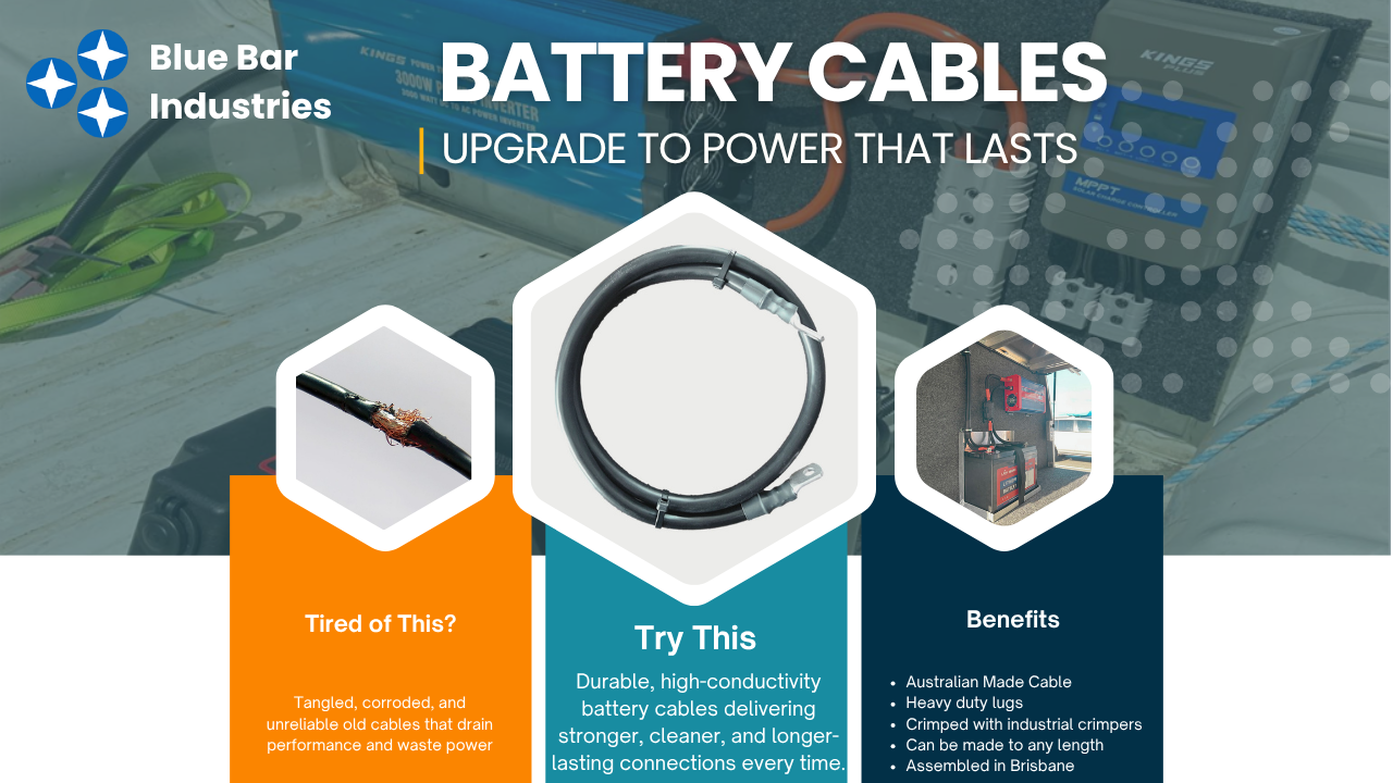
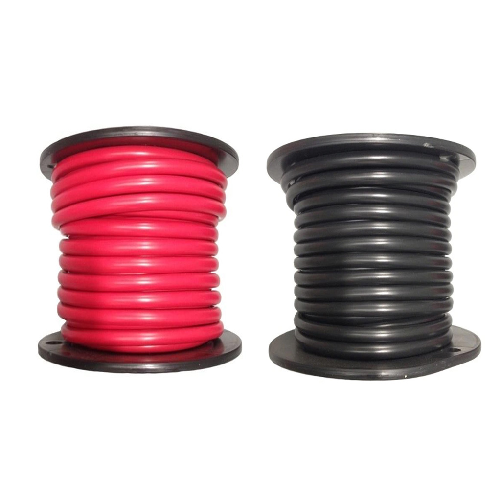
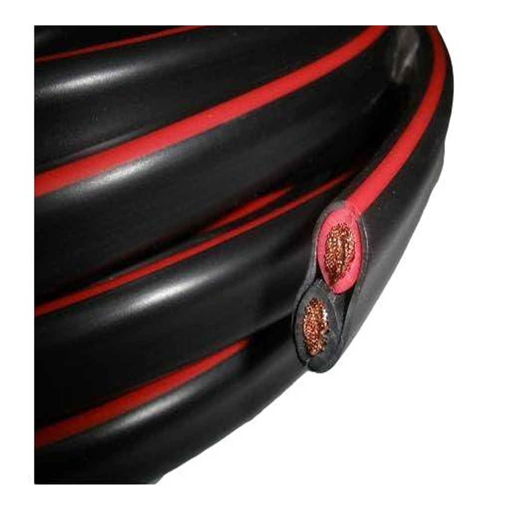
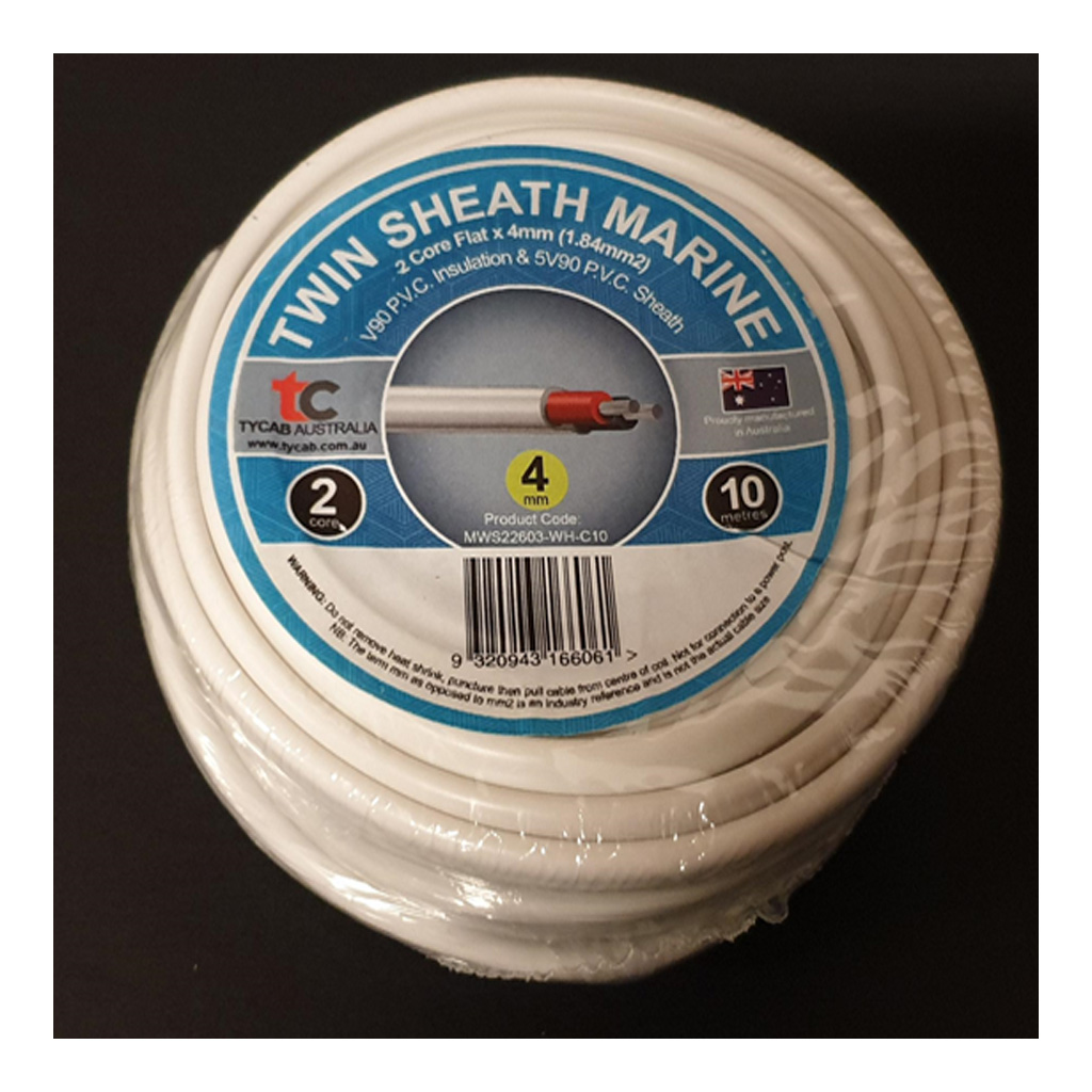
 Cable Lugs
 Cable Lug Assortment Kits
 Cable Lugs Straight Wall Closed
 Cable Glands
 Convoluted Split Tubing
 12/24v Products & Access

 Electrical Connectors
 Solar Powered Products
 LED Lights

 Tools




 Auto Parts & Categories

 Fittings
 Cleaning & Misc

 Clearance & Promotion
Latest News
How to Wire a Marine Switch Panel Safely on Your Boat
Sep
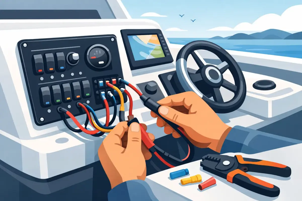
A switch panel should make your boat easier to operate, not create a fault-finding job every time you leave the ramp. If you are working out how to wire marine switch panel circuits, start with a proper power distribution plan. The switches are only the control point. Safe, dependable operation comes from the battery protection, cable size, terminations, negative return and corrosion resistance behind the panel.
A clean 12V or 24V installation also makes future additions simpler. Whether you are fitting deck lights, electronics, pumps or USB charging, each circuit needs protection matched to the load and cable – not just a spare switch that happens to be available.
Plan the marine switch panel before running cable
Start by listing every load the panel will control, its current draw, and whether it needs to operate only when the main battery switch is on. Typical switched circuits include navigation lights, cabin lights, deck lights, livewell or washdown pumps, electronics, accessory sockets and a horn.
Some equipment needs a different arrangement. An automatic bilge pump commonly has a permanently powered, separately fused feed so the float switch can operate while the boat is unattended. That circuit may also include a manual override at the panel, but it must not rely solely on the panel switch. Follow the pump manufacturer’s wiring diagram for the correct configuration.
Check whether your switch panel has built-in circuit breakers, resettable breakers or no protection at all. A pre-wired panel with breakers can reduce installation time, but the breaker ratings still need to suit the cable and connected load. A basic rocker-switch panel generally requires an external fuse block or individual inline fuses for every circuit.
Before buying cable, measure the run from the battery or distribution point to the panel and then from the panel to each load. Include the return path to the negative busbar. On a small boat, voltage drop can still be significant, particularly on long runs to bow lights, pumps and refrigeration. A load can work at the dock yet perform poorly once battery voltage falls under real use.
The basic marine switch panel wiring layout
Most DC switch panels follow a straightforward path:
Battery positive -> main fuse or circuit breaker -> battery isolation switch -> positive distribution busbar or fuse block -> panel switch or breaker -> load.
The negative side returns from each load to a negative busbar, then back to battery negative. Do not use the hull, engine block or a random mounting screw as a return conductor. Every DC load should have a suitably sized negative cable back to the common negative bus.
The main fuse or breaker protects the cable leaving the battery. It should be installed as close to the battery positive terminal as practical. If the unfused section of cable rubs through on a sharp edge or gets crushed, the battery can supply enough current to cause serious heat, damaged wiring or fire.
A battery isolation switch is strongly recommended for house circuits. It lets you isolate non-essential power during maintenance, storage or an electrical fault. On boats with separate start and house banks, the switch panel is normally fed from the house battery bank, not directly from the engine start battery.
Positive feed and circuit protection
Use a main feed cable sized for the total expected panel load, allowing for cable run length and future accessories. The main fuse rating must protect that cable. From the distribution point, each branch circuit needs its own fuse or breaker selected for the branch cable size and equipment requirements.
For example, a 3A LED lighting load does not justify fitting a 15A fuse simply because one is on hand. In a fault, that higher-rated fuse may allow a small cable to overheat before it opens. Fit the fuse to protect the wire first, then confirm it can handle the normal operating current of the device.
Many panels are supplied with a positive input terminal and separate switched outputs. Run the protected supply into the panel input, then run a dedicated positive cable from each output to its load. Label both ends of every cable as you install it. A few minutes spent labelling now can save hours later when tracing a fault under the console.
Negative busbar and returns
Install a marine-rated negative busbar in a dry, accessible location near the fuse block or panel. Bring each load’s negative cable back to this busbar rather than joining several returns with loose crimp connections behind the dash.
A busbar creates a central, inspectable return point and keeps voltage drop lower than relying on questionable shared earths. Size the main negative cable from the busbar to the battery to carry the combined load, just as you would the main positive feed.
Choosing cable, terminals and protection
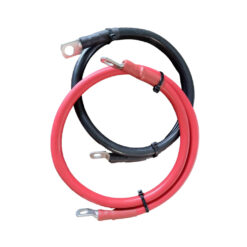
Marine wiring lives with vibration, moisture, salt spray and heat. Automotive cable can be suitable in protected areas, but tinned marine-grade copper cable is the better choice where corrosion resistance matters. It remains flexible, handles harsh environments better and gives more reliable long-term connections.
Cable size depends on current draw, run length and acceptable voltage drop. Navigation lighting and electronics are especially sensitive to low voltage. If a cable run is long, stepping up a cable size is often cheap insurance against dim lights, voltage alarms and intermittent pump performance.
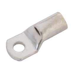
Use quality crimp terminals sized correctly for both the cable and stud. Ring terminals are preferred for battery, busbar and fuse connections because they cannot fall off if a nut loosens. Crimp with the proper tool, then seal the joint with adhesive-lined heat-shrink. Avoid twisting wires together, wrapping them in tape or using household electrical connectors.
Protect cable wherever it passes through a bulkhead, aluminium panel or sharp opening. Fit grommets, split conduit or abrasion-resistant sleeving, and support runs with suitable clips at regular intervals. Keep wiring above the bilge where possible and away from exhaust components, moving steering gear and fuel lines.
How to wire a marine switch panel step by step
With the battery isolated, mount the panel where it is protected from direct spray and can be reached easily from the helm. Leave enough room behind it for terminals, cable bends and future servicing. A panel installed hard against a shallow dash can put constant strain on connectors.
Run the main positive feed from the battery area through the main fuse and isolation switch to the panel supply or positive distribution busbar. Run the matching main negative cable from battery negative to the negative busbar. Do not connect the battery terminals yet.
Next, fit each branch circuit. Connect the panel output to the positive wire for the relevant load, and connect the load negative to the negative busbar. Install the correctly rated fuse or breaker for that circuit. If the panel uses illuminated switches, check whether it requires a separate negative connection for the switch illumination.
When all terminations are complete, inspect each connection for correct crimping, heat-shrink coverage and strain relief. Confirm no bare conductor is exposed and that every cable is secured. Only then reconnect the battery, energise the main isolator and test one circuit at a time.
Use a multimeter during testing. Check battery voltage at the panel input, then measure voltage at the load while it is operating. A notable voltage drop points to undersized cable, a poor crimp, corrosion or an inadequate negative return. Do not keep increasing fuse size to solve a performance problem.
Common marine panel wiring mistakes
The most common fault is treating a switch as circuit protection. Switches turn circuits on and off, while fuses and breakers protect cable from overload and short circuits. Both are required.
Another frequent issue is undersized cable selected only by current draw, without accounting for cable length. This is particularly common on trailer boats where wiring runs from the stern battery to bow-mounted lights or pumps. The third is poor termination practice: non-tinned terminals, unsealed joins and cable unsupported behind the dash soon corrode or fail under vibration.
Avoid mixing AC and DC wiring in the same unprotected bundle. If your vessel has shore power or an inverter system, keep 240V AC work separate and use a qualified electrician or marine installer where required. Compliance obligations can vary by vessel type, survey status and installation scope, so check the applicable Australian requirements before altering critical systems.
For practical 12V and 24V work, Bluebar Industries supplies the cable, terminals, connectors, fuse hardware and cable protection needed to build a serviceable installation rather than a temporary fix.
A well-wired marine switch panel is one you can understand at a glance six months from now. Leave a little spare capacity, keep a circuit diagram with the boat paperwork, and use components that will stand up to salt, vibration and the next long run offshore.